Audio Balun Circuit Diagram
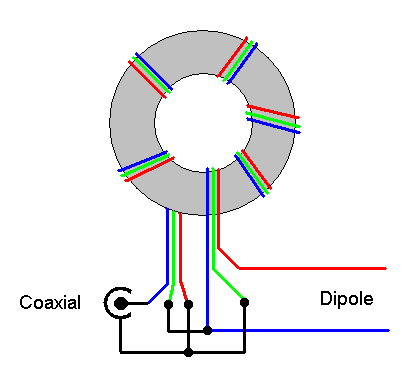
Wiring diagram hf balun Current balun 1 Impedance baluns balun
Using Baluns and RF Components for Impedance Matching - EEWeb
Balun guanella current radio step construction qrp iw5edi type ham next Balun circuit application Receive coil schematic. design of a single receiver coil with the balun
Balun hf wiring diagram voltage wire dipole schematic homebrew ferrite rod dipoles radio m0ukd trifilar
Step-by-step construction of a 4:1 current-type balunCoil receiver balun circuit schematic receive passive detuning Nooelec balun one nineBalun schematic proposed.
Ea4eoz, an amateur radio electronic enthusiast: build your own hf balunBalun nooelec sdr rsp1 antenna swling eevblog rf Balun hf diagram wiring voltage ferrite wire rod homebrew dipoles turn dipole trifilar m0ukd ugly radio fr bandwidth unun 1to1Balun schematic additionally transistors bias.

Wiring diagram hf balun
Balun 868mhzBalun voltage dipole microwave marki Antenna balun current ohm 50 dk7zb baluns coax building schema dipole cable yagi ohms 6m element antennas fan turns wireBalun circuit 868mhz circuitlab filter description.
Balun unun winding endfed qslBalun hf build antenna homebrew radio center diagram wiring amateur own electronic coaxial circuit ham ohm antennas dummy load enthusiast Block diagram and schematic of the proposed balun.Using baluns and rf components for impedance matching.
Balun diagram hf wiring transformer current line core transmission baluns analysis
Dk7zb balunsCircuit schematic of the active balun. additionally, transistors Wiring diagram hf balun.
.


